We are innovative in Electrical, Instrument and Telecommunications. Improvements in performance, cost and schedule follow.
The need for innovation
|
In this section, we discuss Innovative Substation Design. We take a look at current practices, identify problems, and present conceptual solutions.
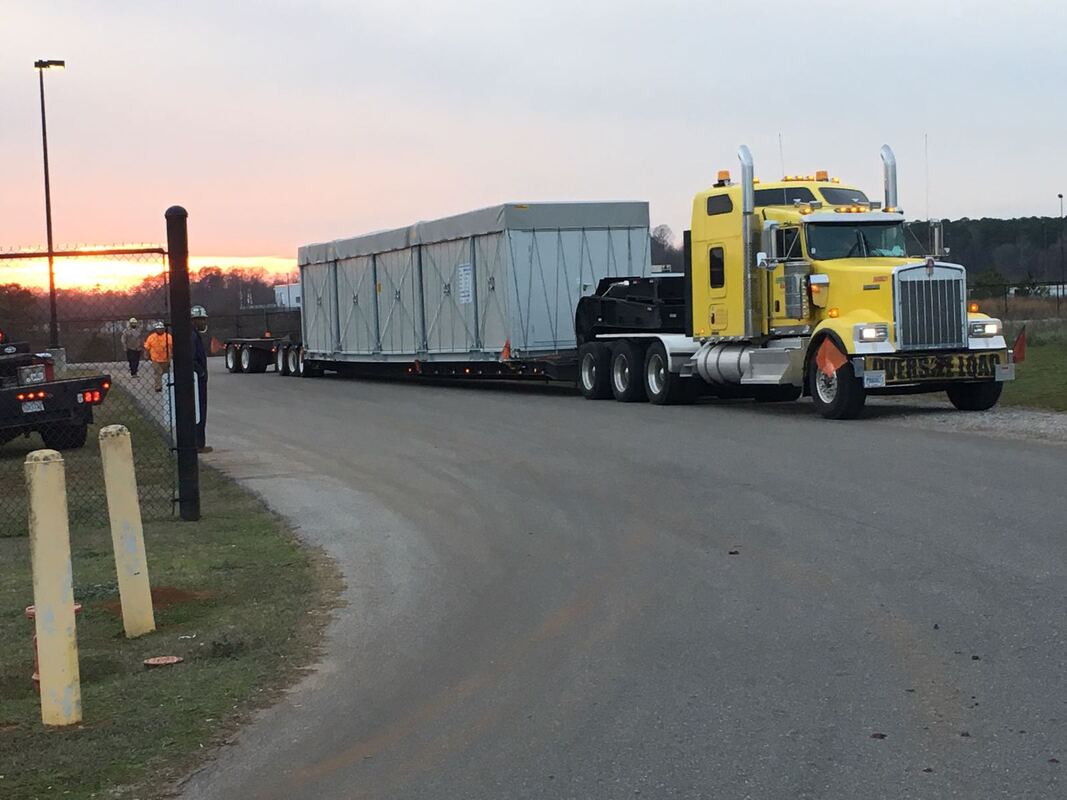
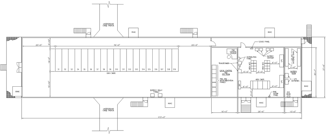
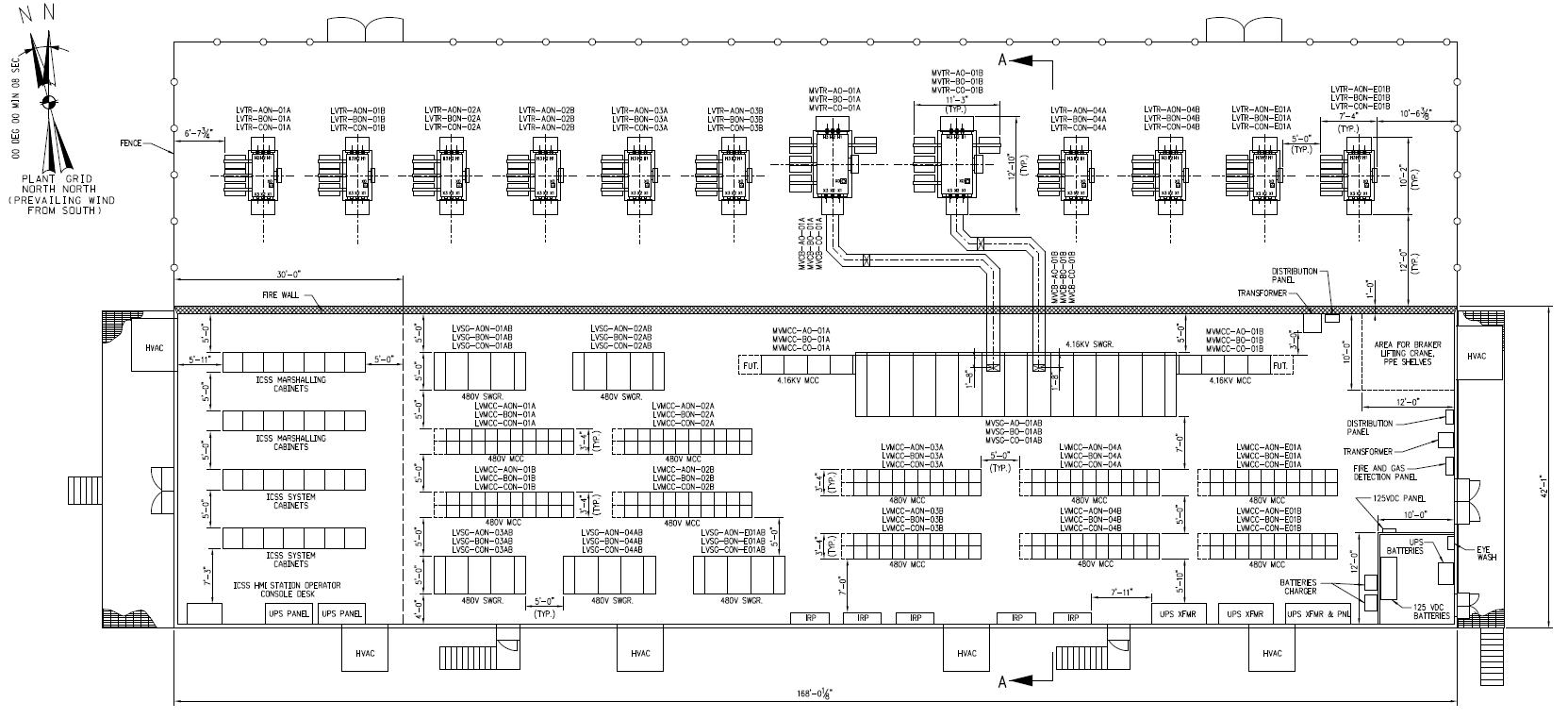
What had happened? During the onset of Mechanical Completion and Commissioning activities of a large Ethane Cracking Plant, it was immediately evident that the lack of progress (according to the schedule) of electrical and instrument cable installation would be a big problem, and potentially hold up plant commissioning. The cable tray and thus cable installation was hindered from progressing because other construction activities were not complete on time. Overruns and delays had already consumed the schedule float. The only option available was to accelerate manhours. The management ramped up the manpower to double, sometimes triple shifts. The tempers rose, but more so the cost. Evolution of cable installations Instrumentation: In a past refinery modernization program (Caltex/Chevron) in the 1990, there was an enormous amount of instrument cabling and cable trays installed, to connect the sensors and actuators to the central control room. These days, virtually all long-run cables are replaced by fiber optic data highways. Gone are the problems with cable tray installation! Electrical: The installation design and methods today are very much the same as they were 20-30 years ago. High voltage and some medium voltage cables would be below the ground, while 600V and less would be above ground. The substation would be located OSBL (Outside Battery Limits), meaning that it was located in a safe area - normally on the other side of the road, while the plant equipment was deemed to be ISBL (Inside Battery Limits). Low voltage cables would exit from below the substation (Figure 1), and make there way to the plant They would cross roads and rise up to make there way to the plant (Figure 2). These interconnecting cables were a major concern. Solutions: What if the low voltage portion of the substation (we ill now call this the eHouse) was on the integrated into the process module? How would that change things?
The impact of moving the eHouse to the process module however does have some drawbacks and challenges (discussed later), but overall, there are significant advantages. |
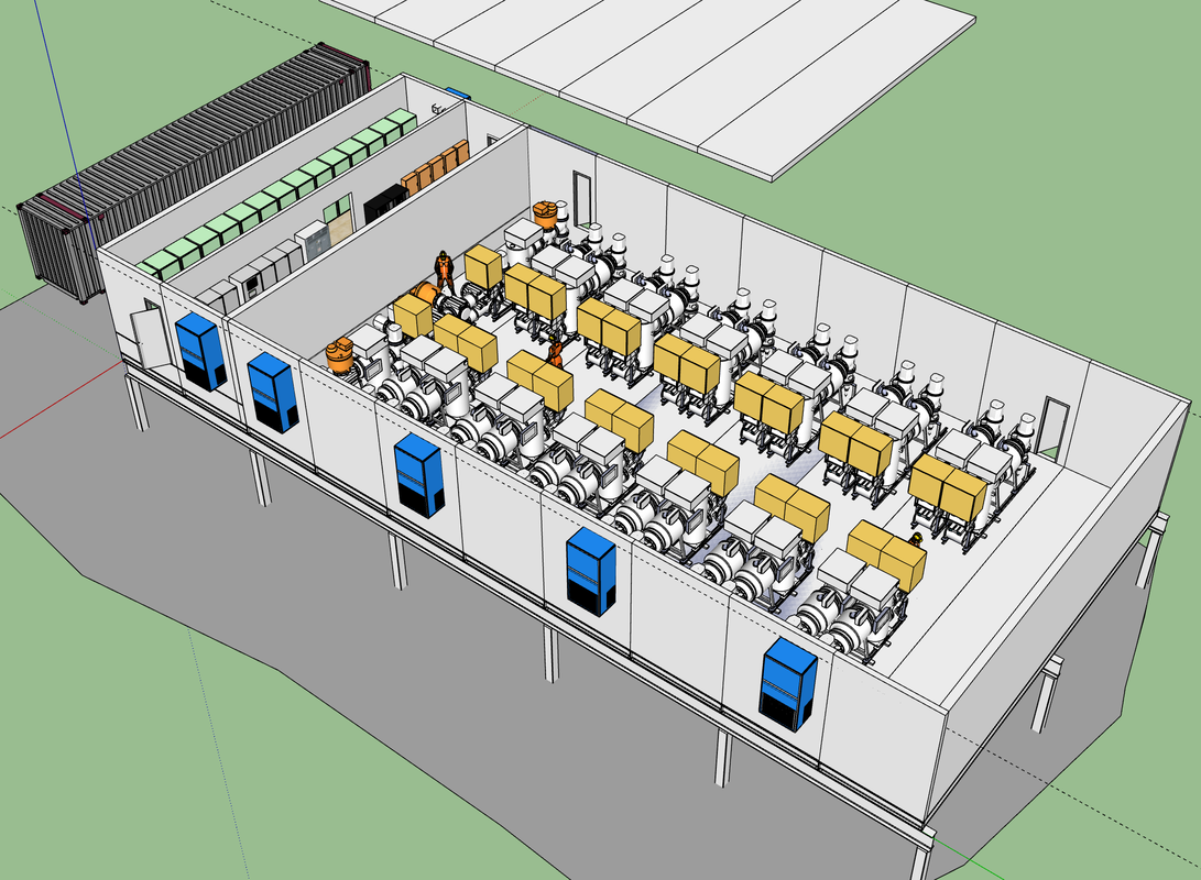
69kV substation, Modular 3D model
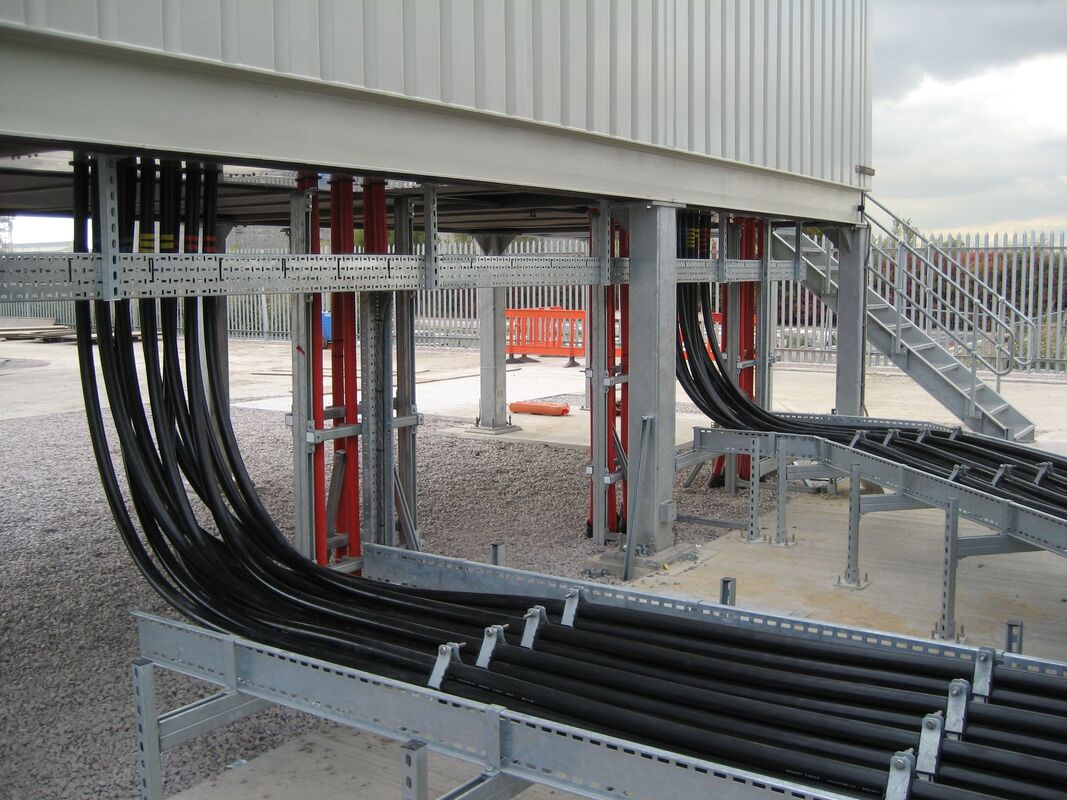
Low voltage cables exiting from below the substation
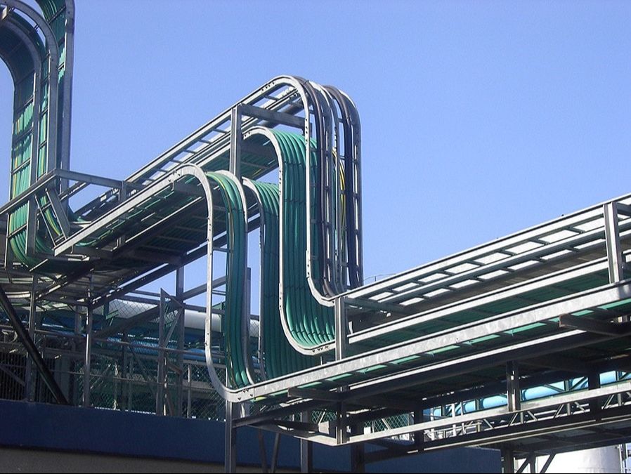
Cable tray installation rising up over roadway / to elevated pipe rack
|
Design Strategy
|
Two separate improvement areas were now identified:
Gfoellner, a company located in Austria (www.gfoellner.at/en/) had made considerable strides in modularization. Modules took on the form of large containers that could be transported by road. Following on from this design a Gas Insulated Substation module was conceptualized. (See High Voltage Substations below) For the Low Voltage solution, the same modulus would be used as the High Voltage solutions, and further the same modulus would be used for the Medium Voltage solution. At this stage, the design starts to take form:
|
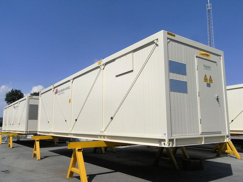
Containerized electrical building [Gfoellner]
Containerized building being transported by road. [Gfoellner]
|
High Voltage Substations
|
In a previous project (Lake Charles Ethane Cracker), a 69kV dual bus GIS lineup was installed in a concrete building, as one continues line. First, the building needed to be complete, and then the switchgear was installed, one-by-one. The installation, hook-up and commissioning took considerable time with all tasks on the critical path.
In this project, a similar continuous lineup (Figure 1) was considered, however, instead of a concrete building, it would be in a packaged steel building, with construction splits. The design allowed the complete substation to be built and tested off-site, which was one step in the right direction. The design could be improved, particularly when considering it from a commissioning standpoint. The dimensions of the building were considerable, with limited shipping options. Figure 2 shows a conceptual innovative modular solution. In this design, the substation is completely built offsite. Shipping, lifting and re-assembly was simplified. A modulus of 3m wide x about 14m long is provisionally established as the base modulus. (Figure 2 indicates 12mL) |
69kV substation, Traditional design
69kV substation, Modular design
|
Medium and Low Voltage Power Supply Configurations
|
The traditional design approach is shown in Figure 3, Case 3. In this case, there is a common MV/LV substation, with MV/LV cables between the electrical building and the process module. The cable routing is typically as shown in Figure 1 and 2. As discussed, the disadvantage of this solution is that work can be held up due to construction delays. This is considered the base case, upon which various improvements are made.
Case 2: In this case, it can be seen that the low voltage MCCs have been relocated from the main substation to a electrical building on the process module, while the 480V switchgear remains in the substation.
Case 1B: In this case, the LV switchgear and MV/LV transformers are moved to the process module electrical building.
Case 1A: In this case, the objective is to develop an integrated close-coupled solution, that endeavors to eliminate the cabling between the LV switchgear and the LV MCCs. This is a case for further study. |
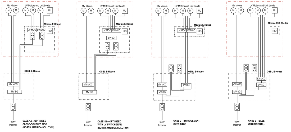
Alternative electrical distribution solutions
|
Medium Voltage Substations
|
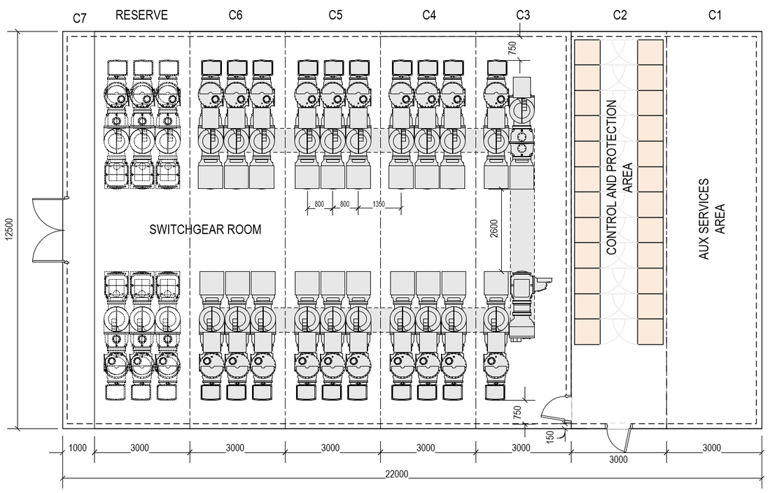
A traditional design approach was also adopted for the Medium/Low voltage substations. The layout included a mix of 13.8kV distribution and motor starting (large loads), 4.16kV motor starting switchgear / MCCs, and 480V switchgear and MCCs. AC and DC UPS systems were additionally provided, with separate battery room. Oil-cooled (ONAN) transformers were located outside the building, and connected using rigid air-insulated bus duct.
The building dimensions were 51mL x 14.3mW x 4.55mH. Construction splits estimated at 6 pieces. In the new modular design, the ONAN transformers are retained, and the MV switchgear is either fed by cables or rigid bus duct. The design takes the conceptual form:
Medium / Low voltage substation (Traditional)
|
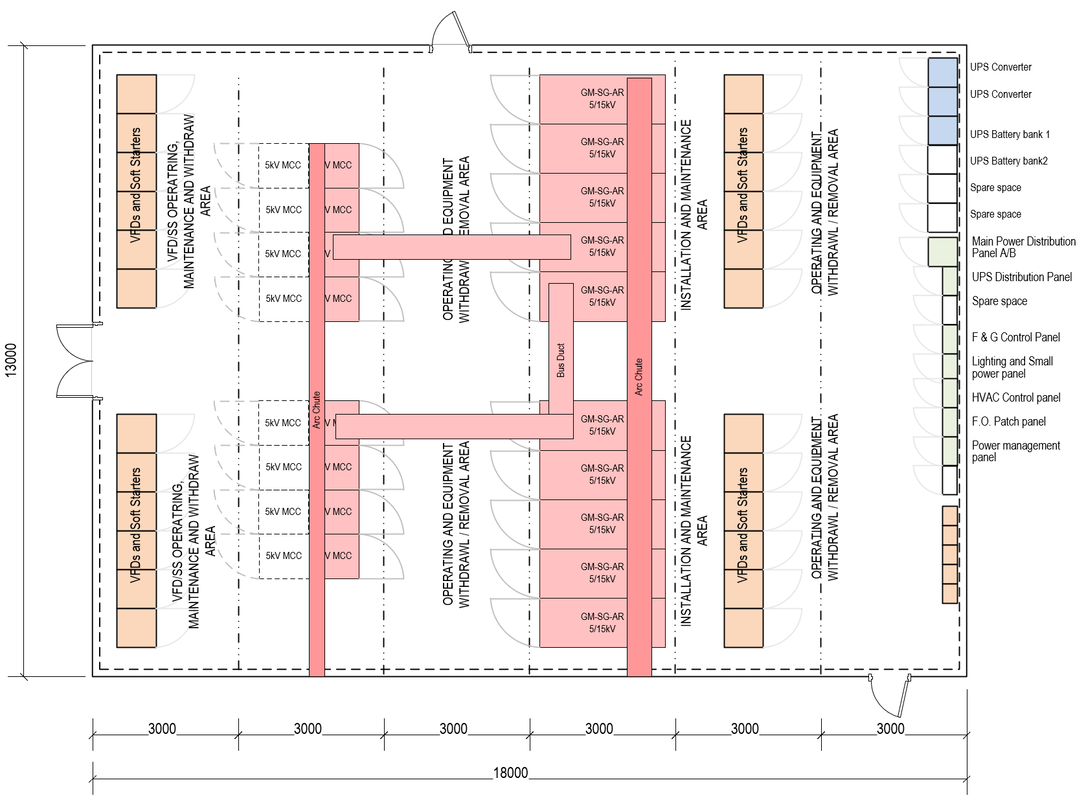
Conceptual Modular design of Medium Voltage Substation.
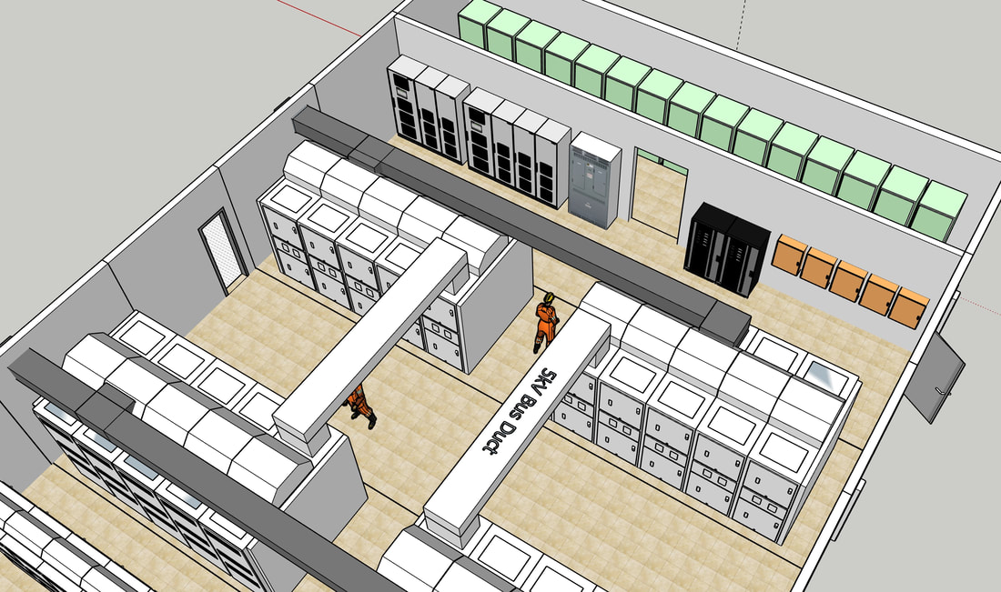
Conceptual Modular design of Medium Voltage Substation, 3D perspective
|
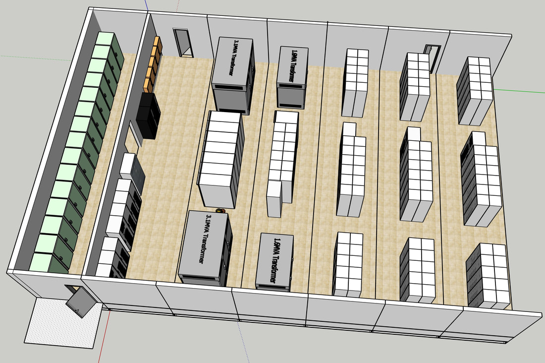
Low Voltage Substations
|
In the case of a Low Voltage solution (eHouse), we follow the same approach as for the medium and high voltage structural design. A typical low voltage solution could comprise the following, Figure 1, from left to right:
The system is fully redundant, meaning either the power supply to a load is either fed from Bus A or Bus B, but not both. It provides for 66% of the load from a normal power supply and the remainder 34% from the essential power supply. Capacity summary Normal power, Bus A (Bus B is mirror image)
Essential power, Bus A (Bus B is mirror image)
|
Low voltage modularized substation (eHouse)
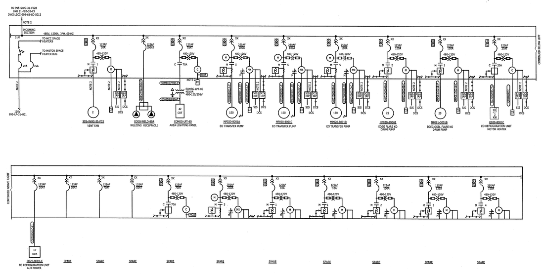
Typical one line / single line diagram of 480V MCC, showing the incomer (top left) and the feeders to the respective loads.
|
Contracting Strategy
|
Apart from the design, we need to establish our contracting strategy.
In the case of the HV substation, Figure provides a simple strategy as an example. An explanation is provided: Building envelope: this is provided by the building manufacture, together with all building outfitting accessories. Normally, all of these items would be sourced locally. Secondary equipment: such as UPS, HVAC and fire suppression may or may not be sourced locally. These items would normally be on teh Preferred Vendors List, and would be subject to approval. Main equipment: such as Gas Insulated Switchgear and Protection/Control would be from a specific maker. |
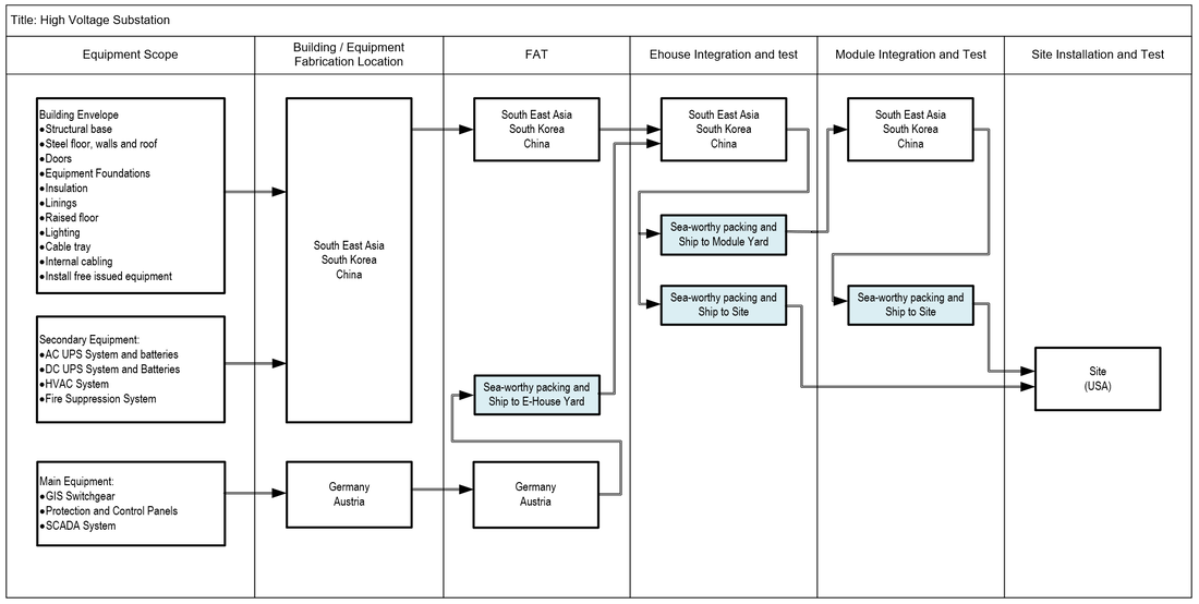
Contracting Strategy for HV Solution Flow Chart
|